Coming from a family of artists and musicians I decided to focus my research on the relationship between music and wood how this could be represented in a larger, playful structure of sounds.
Pythagoras discovered that by hitting an object with a hammer weighing half as much as another (a fundamental note), it produced a vibration frequency or musical note twice as high 2:1 (Octave). By hitting it with a hammer weighing 3:2, it sounded a fifth apart (Perfect Fifth) and a hammer of 4:3 the weight, sounded a fourth apart (Perfect Fourth).
The vibratory curves occur within the struck object and emit varying sounds that we find to be consonant (attractive to hear) and we relate these to musical scales. All other musical notes apart from the fundamental, produce additional frequencies which can be heard simultaneously. They are known as overtones and produce what is known as timbre, allowing a musical note to be heard for more time.
The overtones can be specifically shaped through the tone bars of a Marimba, differentiating itself from the xylophone because of this. The curved, undercut part of a tone bar is responsible for the fundamental note and two additional overtone frequencies, giving this instrument a great timbre.
The fundamental tone produces its vibratory waves with an antinode (marked in green) in the centre of the tone bar. All three variations of the vibratory waves present a node (marked in red) on the extremes of the bar, an opportunity to create a whole to fix them without affecting the note.
The length, width and depth affect the fundamental tone’s frequency: increasing either one with decrease the musical frequency, producing a deeper musical note. Additionally, the orientation and type of wood used will affect the musical note due to its density and capability to transmit sound. I chose to use Poplar for this project due to it being a low-density hardwood (500 Kg/m3) with not many knots and a good capability to transmit sound (5080 m/sec).
In order to form a large structure, I decided to support the tone bars through a tensegrity membrane similar to the Moom Pavilion. The tone bars are aligned in rows, which are fixed on both ends and individually act in compression. Tension cables join each tone bar to the adjacent ones through the vibratory waves’ node. Each row of tone bars is half offset to the adjacent row. The combination of diagonal tension and linear compression gives the structural integrity and creates a vertical lift.
Through digital explorations, I was able to configure a tunnel-like structure that would support 39 tone bars in 7 rows: 4 rows are composed of 6 tone bars each and sitting intermittingly between them are 3 rows of 5 bars each. Through Grasshopper I was able to automate the process of finding the dimensions for each tone bar according to the desired musical note. Each tone bar was then individually cut and sanded down by hand for the desired overtones before being arranged into a grid and joined with cables, crimps and cable tensioners.
The two adjacent extremes of each row of tone bars were fixed to a base I created to anchor them. The most challenging part of this structure is to accomplish the correct tension for it to form a uniform arch. By expanding the base, additional rows of tone bars can be joined laterally to form a larger range of tone bars with an even larger scale of musical notes.
Inspired by Japanese basketry weaving, Twisted Pellucidity takes this technique into an architectural scale. Through creating a set of twisted modules varied with a standard weave in between, the design flows between closed and open creating potential for naturally ventilated housing in hot regions of the world. It has been designed for disassembly to ease transportation and enable adaptations of the size and shape of the design. Thanks to the module’s structural strength, very thin ply strips were used making the structure light and delicate whilst allowing elegant passage of light.
Research: Material Properties. Physical and Digital Experiments.
The project started with the exploration of weaving patterns and their strength and bending qualities. Through a series of experiments I have tested a number of single and double curvatures that could be potentially applied on an architectural scale.
Since bending quality of plywood, whether as a woven sheet or as a singular strip, has always been of interest, I have started looking into combining both of those methods. Thanks to bending, large volumes can be created – which seemed ideal for potential enclosure areas. I have therefore decided to research further into the bend-active qualities of plywood. Starting with a single bend, I have developed the geometry into a triple – twist which created a very structurally strong, symmetrical module. Through Grasshopper scripting of the observed geometry of the physical model I have gained a thorough understanding of the behaviour of twisted strip of plywood which I then further enhanced and through a number of Kangaroo physical simulations I have gained a deep understanding of forces acting on a bent and twisted three times strip of plywood. Those experiments helped explain and understand why and how does a strip of plywood gain an extraordinary structural strength.
Twisting and bending the strip showed a great impact on the properties of the entire module. Thanks to bend-active and torsional forces acting against each other, the module gains incredible strength in both tension and compression with its strength rising about 10 times in comparison to original elements. This allows for almost never-ending possibilities of use when arrayed in different ways.
As I was particularly interested in how the action I have chosen affected the original material, the natural course of action was to test it in a larger scale as an array and combine it with the original research into weaving patterns and their properties. This has naturally created a Field Condition.
Field Condition is any formal or spatial matrix capable of unifying diverse elements while respecting the identity of each. That leads to the overall shape and extent being highly fluid and less important than the internal relationships of parts which determine the behaviour of the field.
Modules can be added infinitely with the remaining texture woven in between creating a dynamic field condition and an architectural design by starting from the individual element, letting it grow incrementally and defining how it connects to the next one.
Thanks to the overall qualities of the system, the final design became an unexpected result of adding modules and then connecting each the ends to create an enclosed circular space. This can vary in diameter until it reaches the structural strength capabilities of the chosen thickness of plywood. For 0.8mm strips the largest structurally stable diameter is approximately 1m. This could be larger for thicker and wider strips however this required further research.
Construction of the Final Model
Assembly of the final model turned out to be time-consuming but rewarding. Due to great intricacy of the module and a number of connections, it took approximately 80 hours to complete the final model.
Final Model ended up taking shape of a tower – large enough to fit myself in it. This process proved the Field Condition properties of the system allowing to create a variety of designs – displayed tower being one of them.
Overall, it was a challenging but extremely rewarding journey which I am excited to draw further conclusions from in the second semester.
Inspired by the Islamic pattern, I discovered that some of the Islamic tiling pattern in shrine are similar to the Penrose tiling discovered by Sir Roger Penrose. Looking into the Penrose tiling, it has 3 types and they all follows the rule of golden ratio. These Penrose tiling arrangements each form a reflection and five-fold rotational symmetry.
types of Penrose tiling
Penrose tiling pattern following rule of golden ratio
After doing more in-depth research, I discovered that the rhombic triacontahedron which made up of rhombuses has a similarity to the Penrose tiling type P3, also with rhombuses. These two geometric patterns can be arranged such that by using a single module (golden rhombus), we can form a 3D rhombic triacontahedron with the guide of Penrose tiling as a 2D plane pattern.
five-fold rotation symmetry shown in Penrose tiling arrangement
The rhombus modules are folded in different sets of angles, it can form a volumetric space while still follows the grid of Penrose tiling from the top view. These are done in 4 angles: 36 degree, 72 degree, 108 degree, and 144 degree.
components of Penrose landscape
front perspective
cut section
concept model with MDF to show the idea
By doing the physical model with CNC-ing 6mm thick plywood with the desired angle, it allow the folding modules fitting into the shape I wanted. The custom metal bracket in between planes of plywood rhombus also helps in forming the shape. It will also allow insulation and waterproofing which will be further developed next as it comprised of double layer of plywood.
Tensegral Tipi uses mathematical symmetry to produce a structure that is in a state of equilibrium. The Tipi merges the concept of a conventional tipi with the structural stability of a tensegrity construction. A tensegrity construction is characterised by a stable three-dimensional structure consisting of members under tension that are contiguous and members under compression that are not. Tensegrity structures provide the ideal solution to the brief, not only are they mathematically symmetrical, they are self supporting and made of consistent sized components. In addition, they only achieve three-dimensionality once all the elements are equally loaded, meaning that, until the last node is connected, the elements remain in a flat-packed condition, a feature excellent for re-deployability. The compression elements will comprise of bamboo, a highly sustainable, easily sourced and cheap material, whilst the tension elements consist of steel cable, a strong and re-useable material capable of taking the tension necessary to achieve structural stability in the system.
Inspiration
The project began with a study in generating mathematical symmetry using imaginary functions in grasshopper. The use of imaginary numbers created patterns which would be challenging to create manually, all of which were symmetrical either in reflection or rotation. The equation µ(t)= 3√(x+it) created a pattern of straight lines which would combine to create curves in the style of a hyperbolic parabaloid. This outcome would initiate my interest in tensegrity as a way to create beautiful curving geometry through the use of solely straight elements.
Tensegrity Force Testing
Force testing using kangaroo engineering plugin for grasshopper, allowed visualisation of the forces acting on each member of the tensegrity system prior to construction. The first step is to identify the cross sectional area and youngs modulus of the tension and compression elements in the system. This information is applied to a kangaroo physics model, which is already in a state of compression and tension, to reveal the exact force running through each member. The data output is used to analyse if the model can hold its shape and that the materials used can withstand the forces applied to them. In this instance, the hemp rope would have the strength to tension the model, but would not be able to resist the additional force of human touch, resulting in catastrophic failure. A more substantial tensioning material would be required, steel tension cable. In addition, bamboo has a relatively weak shear force, meaning that the twist created from tensioning each end of bamboo would snap the member. To resolve this issue, end caps were developed to spin independently on each bamboo pole, transferring the shear force into the connection.
There would be two stages to the construction process, the tensegrity module and the connections between modules which form the inhabitable space. The tensgrity module was designed for ease of manufacture, all bamboo components are identical in length at 1220mm (material ships in 2440mm lengths). Pre-manufactured aluminium caps are fitted to the ends of each bamboo piece, then assembled into ‘ladders’ with the use of a jig, steel tension cable and cable crimps. Each tensegrity module consists of three identical ‘ladders’, which are twisted to connect to each other in a spiral arrangment. The module has six connection nodes, five of which can be pre-assembled prior to arrival on site. With the connection of the sixth node the module becomes a three-dimensional, stable shape. This technology results in the assembly of modules in-situe in under five minutes. The second stage of connecting the modules to form the inhabitable space, requires the insertion of pre-cut bamboo poles into the longer aluminium end caps, a process which can be completed in a further five minute period.
Applicability
This project has many benefits, namely due to its simplicity, it can be built in a garage without the use of specialist tools, requiring only a saw, drill and pliers. Identical length components means manufacturing is intuitive, efficient and cheap, whilst the speed of deployment, and ease of flat pack storage, could have real benefits in the temporary shelter market.
The Beauty of Curvature proposal seeks a way of developing a curved form created entirely out of flat plywood components, which connect with each other with interlocking slots and do not require any additional fixtures. The project explores the potential of plywood as a self-supporting material, and uses boards as thin as 2.7mm, which significantly reduces the weight and cost of the structure.
The layout of the panels ensures that material waste is reduced to a minimum.
The project has evolved as a result of series of experiments and explorations of different ways of creating curvature from plywood. It initially started as an ambition of bending plywood on a formwork, using vacuum bags and lamination which proved to be non-cost effective, time consuming and not environmentally friendly due to the lamination process. The idea then shifted into curved structure composed out of 2D panels interlocking with each other, which led to its final form.
‘Growth From The Ger’ seeks to analyse the vernacular structure of the traditional nomad home and use parametric thinking to create a deployable structure that can grow by modular.
‘Ger’ meaning ‘home’ is a Mongolian word which describes the portable dwelling. Commonly known as a ‘yurt’, a Turkish word, the yurt offered a sustainable lifestyle for the nomadic tribes of the steppes of Central Asia. It allowed nomads to migrate seasonally, catering to their livestock, water access and in relation to the status of wars/conflicts. An ancient structure, it has developed in material and joinery, however the concept prominently remaining the same.
Inspiration
Growing up in London, I fell in love with the transportable home when I first visited Mongolia at the age of 17. The symmetrical framework and circulating walls create a calm and peaceful environment. In the winter it keeps the cold out and in the summer keeps the heat out. The traditional understanding of placement and ways of living within it, which seems similar to a place of worship, builds upon the concept of respect towards life and its offerings.
Understanding the beauty of the lifestyle, I also understand the struggles that come with it and with these in mind, I wanted to explore ways of solving it whilst keeping the positives of the lifestyle it offers.
Pros: Deployable, transportable, timber, vernacular, can be assembled and dissembled by one family, can vary in size/easily scaleable depending on user, low maintenance, sustainable, autonomous.
Cons: Difficult to sustain singularly, not water proof, no privacy, no separation of space, low ceiling height, can’t attach gers together, low levels of security.
A digital render produced on Rhino, showing the steps of building a ger in elevation.
Lattice Analysis and Testing
To understand the possibilities of the lattice wall, I created a 1:20 plywood model using 1mm fishing wire as the joinery. This created various circular spirals and curves. The loose fit of the wire within the holes of timber pieces allowed such curves to happen and created an expanding body. The expansion and flexible joinery allows it to cover a wider space in relation to the amount of material used.
A series of photos showing the expansion and various curves of the lattice model.
I created the same latticework at 1:2 scale to see if the same curvature was created.
1:2 plywood model testing flexible joinery and curvature at large scale.
Locking the curve to create a habitable space. I did this by changing the types of joints in different parts of the structure.
A series of images showing the deployment of the structure and locked into place.
To create a smoother and more beautiful curve I change the baton to a dowel and densify the structure.
Model photo of curve in full expansion.
To lock the lattice curve in expansion I extrude legs that meet the ground and tie together.
Model photo of curve in full expansion and locked in place.
Manufacturing and assembly
Diagram of the construction sequence of model.A series of photos showing 1:2 scale model being deployed.1:2 prototype made from 18mmx18mm square plywood sticks joined together by twine.
The model made from sheet plywood cost approximately £30 and took one working day to make for one person. However, a more sustainable material and process needed to be considered as the process of making plywood contradicted this.
Photo showing the modular growth of the module. Models made from 18x18mm square sticks of softwood timber and joined together with twine.
This model can be made by one person with the use of a wood workshop. The timber pieces were bought at 18mm x 95mm x 4200mm, 13 pieces of these were enough to make three modules, roughly costing £170 in total. Each module takes approximately 5 hours to construct, this involves the tying of the measured length twine joints. The structure is lightweight and each module is easily transportable by one person.
Growth from the ger: modular growth
Digital render of modules arrayed together at angles, produced on Grasshopper and Rhino. Perspective view.Digital render of modules arrayed together at angles, produced on Grasshopper and Rhino. Perspective view.Digital render of modules arrayed together at angles, produced on Grasshopper and Rhino. Plan view.Digital render of modules arrayed together at angles, produced on Grasshopper and Rhino. Diagram showing the plan functions of each space and modules.
A minimal surface is the surface of minimal area between any given boundaries. In nature such shapes result from an equilibrium of homogeneous tension, e.g. in a soap film.
Minimal surfaces have a constant mean curvature of zero, i.e. the sum of the principal curvatures at each point is zero. Particularly fascinating are minimal surfaces that have a crystalline structure, in the sense of repeating themselves in three dimensions, in other words being triply periodic.
Many triply periodic minimal surfaces are known. The first examples of TPMS were the surfaces described by Schwarz in 1865, followed by a surface described by his student Neovius in 1883. In 1970 Alan Schoen, a then NASA scientist, described 12 more TPMS, and in 1989 H. Karcher proved their existence.
My research into grid structures with the goal of simplifying fabrication through repetitive elements prompted an exploration of TPMS. The highly symmetrical and optimised physical properties of a TPMS, in particular the Gyroid surface, inspired my studio proposal, Minimal Matters.
Gyroid: left: Fundamental region, middle: Surface patch, right: Cubic unit cell
Evolution of a Gyroid Surface
The gyroid is an infinitely connected periodic minimal surface discovered by Schoen in 1970. It has three-fold rotational symmetry but no embedded straight lines or mirror symmetries.
The boundary of the surface patch is based on the six faces of a cube. Eight of the surface patch forms the cubic unit cell of a Gyroid.
For every patch formed by the six edges, only three of them is connected with the surrounding patches.
Note that the cube faces are not symmetry planes. There is a C3 symmetry axis along the cube diagonal from the upper right corner when repeating the cubic unit cell.
Curiously, like some other triply periodic minimal surfaces, the gyroid surface can be trigonometrically approximated by a short equation:
cos(x)sin(y)+cos(y)sin(z)+cos(z)sin(x)=0
Using Grasshopper and the ‘Iso Surface’ component of Millipede, many TPMS can be generated by finding the result of it’s implicit equation.
Standard F(x,y,z) functions of minimal surfaces are defined to determine the shapes within a bounding box. The resulting points form a mesh that describes the geometry.
TPMS Grasshopper Definition
A cube of points are constructed via a domain and fed into a function. Inputs of standard minimal surfaces are used as the equation.
The resulting function values are plugged into Millipede’s Isosurface component.
The bounding box sets up the restrictions for the geometry.
Xres, Yres, Zres [Integer]: The resolution of the three dimensional grid.
Isovalue: The ‘IsoValue’ input generates the surface in shells, with zero being the outermost shell, and moving inward.
Merge: If true the resulting mesh will have its coinciding vertices fused and will look smoother (continuous, not faceted)
Triply Periodic Minimal Surfaces generated by their implicit equations
The above diagrams show Triply Periodic Minimal surfaces generated from their implicit mathematical equations. The functions are plotted with a domain of negative and positive Pi. By adjusting the domain to 0.5, the surface patch can be generated.
Many TPMS can best be understood and constructed in terms of fundamental regions (or surface patches) bounded by mirror symmetry planes. For example, the fundamental region formed in the kaleidoscopic cell of a Schwarz P surface is a quadrilateral in a tetrahedron, which 1 /48 of a cube (shown below left). Four of which create the surface patch. The right image shows a cubic unit cell, comprising eight of the surface patch.
Schwarz P: left: Fundamental region, middle: Surface patch, right: Cubic unit cell Evolution of a Schwarz P Surface
Schoen’s batwing surface has the quadrilateral tetrahedron (1/48 of a cube) as it’s kaleidoscopic cell, with a C2 symmetry axis. As shown in the evolution diagram below, the appearance of two fundamental regions is the source of the name ‘batwing’. Twelve of the fundamental regions form the cubic unit cell; however this is still only 1/8 of the complete minimal surface lattice cell.
Schoen’s PA Batwing Surface: left: kaleidoscopic cell, middle: Fundamental region, right: Cubic unit cellEvolution of a Schoen’s Pa (Batwing) Surface
Inspired by the highly symmetrical and optimised physical properties of a triply periodic minimal surface, ‘Minimal Matters’ aims to create an explorative, meditative and interactive experience for visitors. It is a strained grid shell utilising the geometrical benefits of an asymptotic curve network; digitally designed via algorithmic rules to minimise material, cost, and construction time.
The proposal takes the form of a crystalline structure found in nature, interpreted through parametric design into a timber grid art piece. In the sense of repeating themselves in three dimensions, a gyroid is an infinitely connected triply periodic minimal surface. A minimal surface is a single surface articulation which minimises that amount of surface needed to occupy space. The proposal represents restoring a balance in energy, taking only that of the earth’s resources required to fulfil the form. Our inability to distinguish our needs from our greeds leads to excessive desires for life’s commodities. The efficiency of the design complements the beauty of rotational symmetry of a single node.
The lattice structure will create foot and hand holds to help climbers onto the series of sloping platforms; allowing users to survey the desert camp from different perspectives.
More than just a climbable structure, Minimal Matters is to be a resting place for festival-goers and a shelter from the strong sun of the site. The layers of grids cast shadows of varied patterns throughout the day. At night, LED lighting along the lamellas will celebrate it’s form and illuminate the playa.
1.5mm Plywood Prototype – 600x600x600mm
Inspired by nature, the proposal brings a parametrically designed structure into the realm of physical interaction. The piece is a culmination of thorough research and physical exploration of timber’s potential. The combination of conceptual bravery matched with architectural reality seeks an architecture of playfulness and beauty which will respond to the inclusive environment of Burning Man. It will celebrate a new design method for timber grid construction, and symbolise the harmony between nature and computational design.
Through extensive research into the construction of grid shells, as well as differential geometry, I present a design solution for a complex grid structure inspired by the highly symmetrical and optimised physical properties of a triply periodic minimal surface. The proposal implements the asymptotic design method of Eike Schling and his team at Technical University of Munich.
‘Minimal Matters’ utilises the several geometric benefits of an asymptotic curve network to optimise cost and fabrication. From differential geometry, it is determined asymptotic curves are not curved in the surface normal direction. As opposed to traditional gridshells, this means they can be formed from straight, planar strips perpendicular to the surface. In combination with 90° intersections that appear on all minimal surfaces (soap films) this method offers a simple and affordable construction method. Asymptotic curves have a vanishing normal curvature, and thus only exist on anticlastic surface-regions.
Asymptotic curves can be plotted on any anticlastic surface using differential geometry.
On minimal surfaces, the deviation angle α is always 45 (due to the bisecting property of asymptotic curves and principle curvature lines). Both principle curvature networks and asymptotic curve networks consist of two families of curves that follow a direction field. The designer can only pick a starting point, but cannot alter their path.
(a) Planes of principle curvature are where the curvature takes its maximum and minimum values. They are always perpendicular, and intersect the tangent plane.
(b) Surface geometry at a generic point on a minimal surface. At any point there are two orthogonal principal directions (Blue), along which the curves on the surface are most convex and concave. Their curvature is quantified by the inverse of the radii (R1 and R2) of circles fitted to the sectional curves along these directions. Exactly between these principal directions are the asymptotic directions (orange), along which the surface curves least.
(c) The direction and magnitude for these directions vary between points on a surface.
(d) Starting from point, lines can be drawn to connect points along the paths of principal and asymptotic directions on the respective surface.
Gyroid TPMS
The next step is to create the asymptotic curve network for the Gyroid minimal surface; chosen from my research into Triply Periodic Minimal Surfaces.
As the designer, I can merely pick a starting point on an anticlastic surface from which two asymptotic paths will originate. It is crucial to understand the behaviour of asymptotic curves and its dependency on the Gaussian curvature of the surface.
Through rotational symmetry, it is resolved to only require six unique strips for the complete grid structure (Seven including the repeated perimeter piece).
The node to node distance, measured along the asymptotic curves, is the only variable information needed to draw the flat and straight strips. They are then cut flat and bent and twisted into an asymptotic support structure.
Plywood Prototype: 600mm cubed
Eight fundamental units complete the cubit unit cell of a Gyroid surface. Due to the scale of the proposal, I have introduced two layers of lamellas. This is to ensure each layer is sufficiently slender to be easily bent and twisted into its target geometry, whilst providing enough stiffness to resist buckling under compression loads.
‘Minimal Matters’ aims to create an explorative, meditative and interactive experience for visitors. It is a strained grid shell utilising the geometrical benefits of an asymptotic curve network; digitally designed via algorithmic rules to minimise material, cost, and construction time.
This year’s brief sees a focus on wood and it’s potential for sustainable design. The students are to explore the extremes of its potential through undertaking and documenting material research through both physical and digital explorations. Brief one will produce a large scale wooden structure for an exhibition held at the university. The research should lead to an architectural system based on a specific species of wood, a specific manufacturing and assembly technique, and is to be part of a full cradle to cradle life cycle.
Wood is one of architecture’s more magnanimous materials, and is celebrated for it’s sustainability, quality and speed of construction. Brief 02 will see our students present a credible scenario for a sustainable community, of which the project’s architectural language should form a continuity with their brief 01 system. What starts a community could be a product or a service and we want our students to understand how as an architect you can intervene to materialise the network that binds these people together around this life cycle.
Below is the briefing document issued to DS10 students:
Coming from a family of artists and musicians I decided to focus my research on the relationship between music and wood how this could be represented in a larger, playful structure of sounds.
Pythagoras discovered that by hitting an object with a hammer weighing half as much as another (a fundamental note), it produced a vibration frequency or musical note twice as high 2:1 (Octave). By hitting it with a hammer weighing 3:2, it sounded a fifth apart (Perfect Fifth) and a hammer of 4:3 the weight, sounded a fourth apart (Perfect Fourth).
The vibratory curves occur within the struck object and emit varying sounds that we find to be consonant (attractive to hear) and we relate these to musical scales. All other musical notes apart from the fundamental, produce additional frequencies which can be heard simultaneously. They are known as overtones and produce what is known as timbre, allowing a musical note to be heard for more time.
The overtones can be specifically shaped through the tone bars of a Marimba, differentiating itself from the xylophone because of this. The curved, undercut part of a tone bar is responsible for the fundamental note and two additional overtone frequencies, giving this instrument a great timbre.
The fundamental tone produces its vibratory waves with an antinode (marked in green) in the centre of the tone bar. All three variations of the vibratory waves present a node (marked in red) on the extremes of the bar, an opportunity to create a whole to fix them without affecting the note.
The length, width and depth affect the fundamental tone’s frequency: increasing either one with decrease the musical frequency, producing a deeper musical note. Additionally, the orientation and type of wood used will affect the musical note due to its density and capability to transmit sound. I chose to use Poplar for this project due to it being a low-density hardwood (500 Kg/m3) with not many knots and a good capability to transmit sound (5080 m/sec).
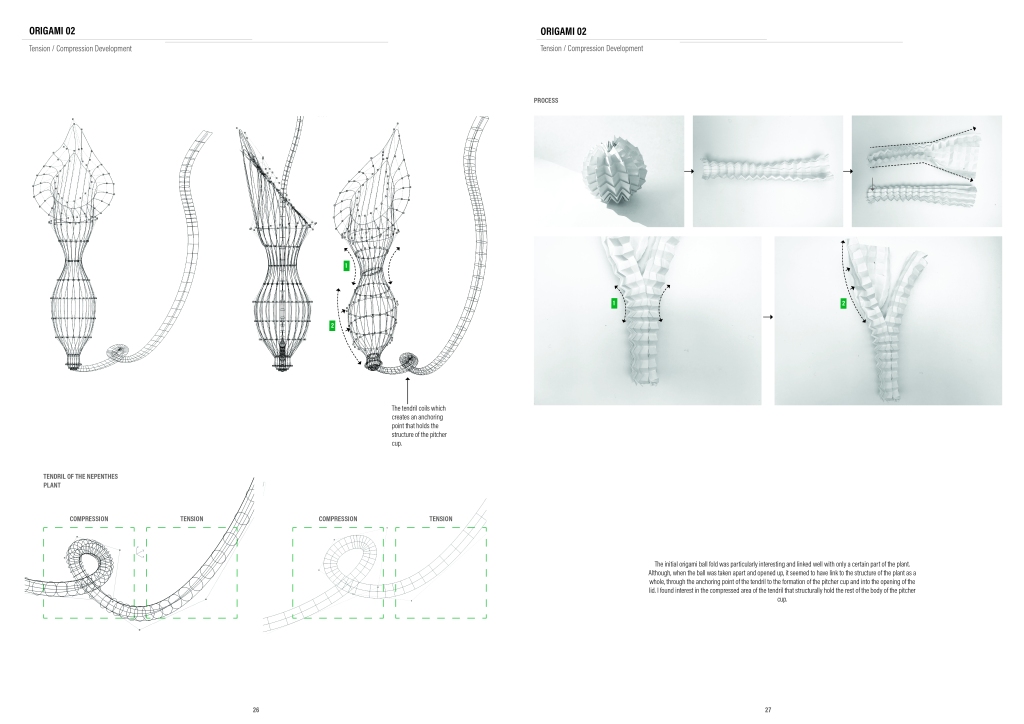
In order to form a large structure, I decided to support the tone bars through a tensegrity membrane similar to the Moom Pavilion. The tone bars are aligned in rows, which are fixed on both ends and individually act in compression. Tension cables join each tone bar to the adjacent ones through the vibratory waves’ node. Each row of tone bars is half offset to the adjacent row. The combination of diagonal tension and linear compression gives the structural integrity and creates a vertical lift.
Through digital explorations, I was able to configure a tunnel-like structure that would support 39 tone bars in 7 rows: 4 rows are composed of 6 tone bars each and sitting intermittingly between them are 3 rows of 5 bars each. Through Grasshopper I was able to automate the process of finding the dimensions for each tone bar according to the desired musical note. Each tone bar was then individually cut and sanded down by hand for the desired overtones before being arranged into a grid and joined with cables, crimps and cable tensioners.
The two adjacent extremes of each row of tone bars were fixed to a base I created to anchor them. The most challenging part of this structure is to accomplish the correct tension for it to form a uniform arch. By expanding the base, additional rows of tone bars can be joined laterally to form a larger range of tone bars with an even larger scale of musical notes.
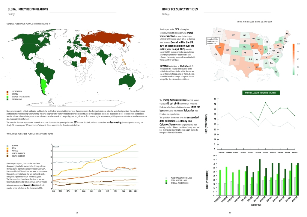
Much can be learned from the biological system of the Victoria Amazonica, also known as the Giant Water Lily. The plant has long generated curiosity about its delicate appearance yet impressive strength which is owed to its exceptional structural characteristics. An intricately webbed system of spines and ribs contributes to the success of the Victoria Amazonica, as it evenly distributes the weight of the plant while leaving pockets to store air and increase buoyancy. Once studied in detail, the branching pattern of the spines and ribs becomes apparent. Each Water Lily is unique, but all follow the same fractal branching pattern which can be defined by the following geometric sequence:
This branching system proves to be most effective for the Victoria Amazonica. Therefore, because of the efficiency of the system, its quick growth, and incredible strength, the plant can become somewhat of an invasive species. While the Lily Pad remains planar, in different forms, its system proves to be equally as strong. Below, the application of the system to different forms is tested.
Ribs are evenly dispersed between spines, lending to the plant’s equally distributed surface weight. In this example, the ribs are roughly spaced 8.3 cm from each other. This can be described with the linear expression: y=(1/8.3)x
Finite Element Method Mesh structurally analyzes how the surface of the Lily Pad is broken up into geometric cells. The FEM of the Pad can be tested for its movement under force and for its elasticity . These diagrams were generated with data from Nature-Inspired Fractal Geometry and Its Applications in Architectural Designs. Asayama, Riane, Sassone. 2014.
Naturally, the model without ribs (left model) was not as strong. However, it had more potential for movement and was still structurally impressive. Going forward, this was used as a base model for form studies.
As the above models proved to be structurally sound, they were scaled up to test their application to a larger model. At 1.5 m, the structure was not as stable because the spacing of the branches increased. Going forward, increased branching will be tested. Added weight will also be applied to see how it affects the stability.
The fern is one of the basic examples of fractals. Fractals are infinitely complex patterns that are self-similar across different scales, created by repeating a simple process over and over in a loop. The Barnsley fern (Example here) shows how graphically beautiful structures can be built from repetitive uses of mathematical formulas.
Fern Parameters
Due to the fractal nature of the fern fronds, the perimeter of the laser cutting took a long time. By simplifying this, I began joining fronds to each other and the large perimeter allowed for enough friction for the fronds to adhere to the adjacent one. I explored this through a series of 4 different frond types (X Axes on matrix below), angles of rotation (Y2, Y3) and distance between each leaf (Y4).
Reciprocal Testing
With the study of many different arrangements of fronds and distances between each leaf in the frond, I was then able to select those that slotted in to the adjacent ones best and began arranging them with more components.
Reciprocal Testing – Flat Component
The arching nature of each individual leaf meant the configuration was only stable once the fitting in of each component had passed the node of the arch. By flattening each component into rectangular members, the friction that allows the components to adhere to each other would be constant throughout the length of the individual part. This means they could now be placed more or less fitted in to the other component, as desired.
Reciprocal Testing – Large Component
I then scaled up the component and attempted to array these as done with the smaller components above. Each component measured 600 mm length-wise and consisted of 5 members (3 facing one way and 2 facing the other, with a gap between them matching the width of each member). They originated from a central “stem” and attached to this by using glue and nails as to allow for easy manufacturing.
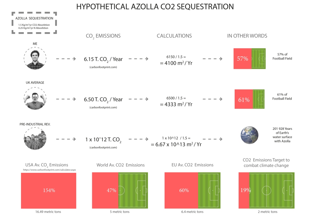
Ferntastic Azolla
Simultaneously, I also became intrigued by a small aquatic fern called Azolla which I thought would be worth exploring too.
What is interesting about this little plant is that it holds the world record in biomass producer – doubling in size from 3-10 days. It is all thanks to its symbiotic relationship with the nitrogen fixing cyanobacterium, Anabaena. This superorganism provides a micro-climate in exchange for nitrate fertilizer.They remain together during the fern’s reproductive cycle. They also have a complimentary photosynthesis, using light from most of the visible spectrum.
BRIEF01 for this year in DS10 began by analysing a plant of our choice that we discover/research from Kew Gardens, London. I started BRIEF01 by researching the Beehive Ginger. I thought the flower’s extensive colours, spiralling bracts and form made the flower quite unique. Having researched the Beehive Ginger, I then discovered that ginger (family) is produced mainly, in China and India. Moving on from researching the flower, I then went on to analysing the form of the flower, as seen below. This exercise helped me distinguish which characteristics of the Beehive Ginger I wanted to model.
DIGITAL MODELLING:
I then went on to creating several different models on Rhino of the Beehive Ginger to better understand the flower.
The first step was to create curves which mimic the beginning, middle and end of a single bract.
The second step was to create a line connecting all the curves together in one direction.
The third step was to use the Loft command to turn the curves into a singular bract.
The fourth step was to use the ArrayPolar command to copy and array the bracts into a cluster.
Finally, to create several clusters of bracts on top of another, as one could find on a Beehive Ginger – I copied and scaled the bracts into different sized clusters to represent the different sizes throughout a singular Beehive Ginger.
The first step is to create a curve and mirror it.
The second step is to use the ArrayPolar command to create a floral shape that will mimic the bract formation of a Beehive Ginger.
The third step is to copy the floral shape, scale and rotate the shape into different angles. This will create the formation of the Beehive Ginger.
The fourth step is to extrude all shapes to give the model volume and dimension.
Due to the interesting shapes the model created, I wanted to play with the light/shadow aspect of the physical model using a solar analysis digitally.
I started by creating a wall made up of my Beehive Ginger model, this was done to create maximum shadows in one area.
I used the DIVA plug-in in Grasshopper and used Chennai, India as my location for the solar analysis. The reason for using Chennai in South India is due to the fact that Ginger is largely produced there. For this reason, Chennai can be a possible site location for BRIEF02.
I used the plug-in for the Winter and Summer Solstice of Chennai, India.
FROM DIGITAL TO PHYSICAL
To create a shift from digital to physical modelling – I decided to mimick the latter digital model physically through laser cutting and using the same alternating methods I used digitally to create the flower. I used corrugated card to create thickness that I achieved through extruding on Rhino. he smaller model did not define the bracts as well as it did digitally due to how densly packed, close and small the bracts were. To create more prominent bracts, I scaled the model up and made the bracts protrude more. I found the alternating angles of the flower shapes that were created interesting as it created corrugated shadows when light is shone through it. I demonstrated this through a torch in a dark room to show this through artificial lighting. As well as demonstrating this through natural daylight which I found more effective. This lead me to believe that this corrugated pattern could be used in daylight rather than artificially. This experiment also helped me proceed to more exploring in BRIEF 01, as the corrugated pattern was an important element rather than the Beehive Ginger flower itself.
COLOUR AND MATERIAL EXPERIMENTS
To mimic the everchanging colours of a Beehive Ginger, I wanted to dye fabric sustainably and mimic the colours. Cheesecloth was my most accessible and cheap material which I could find. As commonly known, dyes are toxic and unsustainable. To create a more sustainable dye process, I used vegetable dyes This included raspberries, red cabbage, beetroot and grated carrot. I started by boiling the vegetable in water to release the natural dye from the vegetable. The next process was to drain and seperate the coloured water and the vegetable. After this, I dipped my cheesecloth into the water and hung it to dry. Then by layering the materials over each other and trimming them to look like the Beehive Ginger.
After dyeing the material as previously done, I cut 4 strips of material, all of the same width and length. I took 2 of these materials and by using PVA glue, I stuck them together to create a thicker and stronger fabric. I then took 1 part PVA glue and 3 parts water to create a paste I dipped all my materials into my paste then hung it to dry. To create a corrugated pattern, I used a hot glue gun and bent the material into the corrugation that the cardboard creates. I then stuck the 2 left over materials on top and beneath the corrugated material which created the corrugated cheesecloth. This was the final product after this experiment was finished. I created a strong wall unit that could evidently create a truss or a house.
I started by doing the processes from my older experiments, including cutting the materials into 4.
Then dipping them into PVA glue to stiffen them.
This was done several times as the shelter had several components to it.
With 12cm intervals, lines were drawn to map out the fold of the corrugation.
The material was then folded over to create the corrugated pattern.
PVA glue was placed on the top of each side of the corrugated cloth
Material was then laid on top to create the surfaces of the corrugation.
The material was then ironed over the PVA glue to seal it with heat and create a strong bind.
To attach corrugated cheesecloth to one another, velcro was used. This makes the shelter easy to assemble and portable.
As a single layer, the corrugated wall held its shape and was a strong structure.
When doubled up to create a full height wall, this became too heavy to be a freestanding structure and toppled over. Just like a house or even a tent, the shelter required beams and foundations.
By placing dowls through the corrugation and leaning them against one another, I was able to create a shelter. Despite the fact that this shelter did not end up how I anticipated, it still held its shape, it is still portable and it can be further improved to create a proper building.
Five years ago this month, more than 1,000 people died and thousands more were injured when Rana Plaza, an eight story-building home to several garment factories, collapsed. Considered to be the worst garment factory disaster of all time, and the worst industrial accident in Bangladesh, the collapse drew worldwide attention to an issue that’s often discussed by consumers but rarely acted upon: the dark side of the garment industry. It took two years for the government to compensate the workers of the tragedy. Arguably little has changed to improve working conditions in the garment industry, or make fast fashion more ethical in the years since. Unlike the 1911 Triangle Shirtwaist factory fire, which ushered in a new era of labor codes and safety measures for American workers, working conditions in the Bangladeshi garment industry remain precarious.
Yet fast fashion not only has consequences for humans, it also has consequences for the environment. The $2.5 trillion fashion industry is the second-largest user of water globally. In the U.S. alone, 13 trillion tons of clothes wind up in landfills each year, leading to soil and groundwater pollution. Greenhouse gas emissions for the industry are also on the rise, and expected to increase by 60% by 2030, with the industry already accounting for 10% of global carbon emissions.
Retailers seem increasingly aware of the environmental impacts of fashion and many have launched sustainability and recycling programs in response. However, terms like “corporate social responsibility” and “sustainability” are thrown around so casually, it makes it difficult for consumers to decipher whether these are just buzzwords or genuine efforts by brands to hold themselves more accountable for the social and environmental ills associated with their industries. In 2014, the average consumer bought 60% more clothing than in 2000 and kept each item for half as long, fueling critics’ arguments that these programs might only promote habits of “guilt free consumption” our throw-away society yearns for. The NYT recently reported that H&M has $4.3 billion worth of unsold inventory, prompting further questions over both the environmental and economic sustainability of fast fashion.’ https://www.bbc.co.uk/news/world-asia-22476774
So,Fast fashion grew out of a demand for affordable, ready-to-wear styles fresh off the catwalk, but how viable is this industry today? Are our appetites for the latest trends really worth the social and environmental costs?
WATER SHORTAGE AND POLLUTION: India exports enormous amounts of water when it exports raw materials such as cotton. The water consumed to grow India’s cotton exports in 2013 would be enough to supply 85% of the country’s 1.24 billion people with 100 litres of water every day for a year. Meanwhile, more than 100 million people in India do not have access to safe water. By exporting more than 7.5m bales of cotton in 2013, India also exported about 38bn cubic metres of virtual water. Those 38bn cubic metres consumed in production of all that cotton weren’t used for anything else. Yet, this amount of water would more than meet the daily needs of 85% of India’s vast population for a year.
IMMENSE QUANTITIES OF WATER: Producing 1kg of cotton in India consumes 10,000 litres of water, on average, according to research done by the Water Footprint Network. In other words, these 10,000 litres of water cannot be used for anything else because it has either evaporated or is too contaminated for reuse. Even with irrigation, US cotton uses just 8,000 litres per kg. The far higher water footprint for India’s cotton is due to inefficient water use and high rates of water pollution — about 50% of all pesticides used in the country are in cotton production.
DEVESTATING CONSEQUENCES: The Aral Sea – Once the 4th largest lake in the world lying between Kazakhstan and Uzebekistan, now gone – mainly because of cotton cultivation. It has been called one of the planet’s worst environmental disasters by the UN. Where there was once a vast water reserve, cotton farms surrounding it used up all of this precious resource leaving behind a toxic, barren wasteland that affected thousands of local habitants. Pesticides and chemical residues that were left behind were so deadly, that many locals were exposed contracted tuberculosis and cancer.
DEADLY POLLUTION: Instead of the Aral Sea, 43 million tonnes of pesticide laden dust is blown in the air every year. The Aral Sea region suffers from the highest rates of throat cancer in the world – representing 80% of the cases of cancer. Hazardous pesticides commonly used for cotton production are often found in nearby water resources. In Uzebekistan, ground water at depths up to 150m is often polluted with pesticides. Around 85% of the population suffers from poor health as a result of unsafe drinking water.
BETWEEN JANUARY 2019 – DECEMBER 2019:
220,890,489,650 tonnes of water used in cotton production globally
164,926 tonnes of organic cotton produced globally
£190 earned by low-wage sweatshop worker annually
25,051,491 tonnes of cotton produced globally
£1,719,201,019 spent on cotton pesticides worldwide
CHILD LABOUR: Around 260 million children are in employment around the world, according to the International Labour Organisation. Of them, the ILO estimates that 170 million are engaged in child labour, defined by the UN as “work for which the child is either too young – work done below the required minimum age – or work which, because of its detrimental nature or conditions, is altogether considered unacceptable for children and is prohibited”. Child labour is forbidden by law in most countries but continues to be rife in some of the poorest parts of the world. The situation is improving. ILO estimates suggest child labour declined by 30% between 2000 and 2012, but still 11% of the world’s children are in situations that deprive them of their right to go to school without interference from work.
MINIMUM WAGE VS LIVING WAGE: The difference between the minimum wage and the living wage. To say instead – The Living Wage is based on the Asia Floor Wage 2013 figure of PPP$725.
HEALTH ANDSAFETY: 50 workers have died and another 5000 are sick due to blasted sand inhalation in denim factories in Turkey. 14 people were killed in a fire at the Bangladesh firm Tarzeen Fashions in 2013. 1,134 garment workers lost their life when a textile factory collapsed in Dhaka in 2013.
FORCED LABOUR: Every year the Governments of Uzbekistan and Turkmenistan, two of the world’s largest exporters of cotton, force hundreds of thousands of people out of their regular jobs and sends them to the cotton fields to toil for weeks in arduous and hazardous conditions. Some have even died in fields from extreme heat and accidents. “You work like a slave from morning till night, not enough food, [we] sleep and wake up hungry again.” – student of Andijan Agricultural Institute, Uzbekistan, September 2016.
WORKING HOURS: 7 days a week is the normal working schedule for garment workers. 14 – 16 hours per day is the average working day in most manufacturing countries. 96 hours per week is the normal working week for a garment worker.
To combat issues with the textile industry, for BRIEF02, I would like to create an ethically and environmentally sustainable factory for textile workers which promotes a healthier wellbeing and a safer work environment. For my concept sketch, I decided to use the Beehive Ginger’s form as the silhouette of the factory. As the plant spirals downward to the stem, I decided to replace the bracts for the corrrugation patterns that I researched during the term. This could be windows, structural support or there for aesthetic purposes. The factory will be based in Chennai, South India as the Beehive Ginger mostly grows in India, and cotton is mostly grown in India as well, with the South of India being largely affected by the sweatshop aspect of the textile industry.